Documentation
Interfaces, Ports Specifications and Connection Validation
Key Information
Interfaces, Port Specifications, and Connection Validation are key in the CELUS Design Platform, designed to facilitate the connection and coordination of CUBOs. Rather than integrating various components traditionally, these features ensure CUBOs can connect and function together effectively in an electronic design.
Port and Interface specifications detail connection parameters, including Signal Maps and compatibility rules, critical for validating CUBO™ connections. This validation checks the alignment of CUBO™ Ports against specific rules to guarantee signal integrity aned functional compatibility.
This streamlined approach enables designers to develop sophisticated electronic circuits efficiently, focusing on the practical aspects of CUBO™ connectivity.
The Ports we have defined are:
I²C
SPI (SPI, QSPI, SPI 3 Wire)
SDIO
ICSP (ICSP AVR, ICSP PIC)
GPIO
Supply
USB
Clock
Crystal
SWD
RF
I²S
A CUBO™ is essentially a modular block within a circuit, characterized by its distinct functionality. While each CUBO™ performs a specific role, a comprehensive circuit requires the integration of multiple such functionalities, interconnected through Ports. This structure facilitates the assembly of complex applications by combining these modular units, each contributing its unique function to the overall system.
Ports are the way devices connect and communicate with each other, defined by specific rules and layouts called the CELUS Standard. Each Port has its own set of signals and rules that ensure devices work well together, whether within the same system (Intra) or with external ones (Inter).
When we talk about Interfaces on the Design Canvas, we're referring to these Ports in action, showing where and how connections happen in your project.
The diagram below shows a simplified version of how a Port is defined.
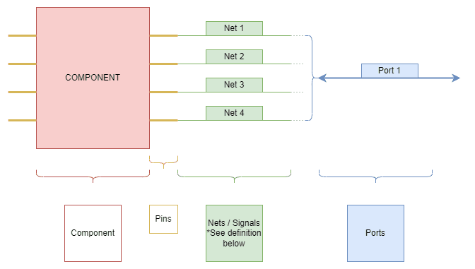
A simplified version of how a Port is defined.
The picture below shows how Ports are defined and their signal mapping.
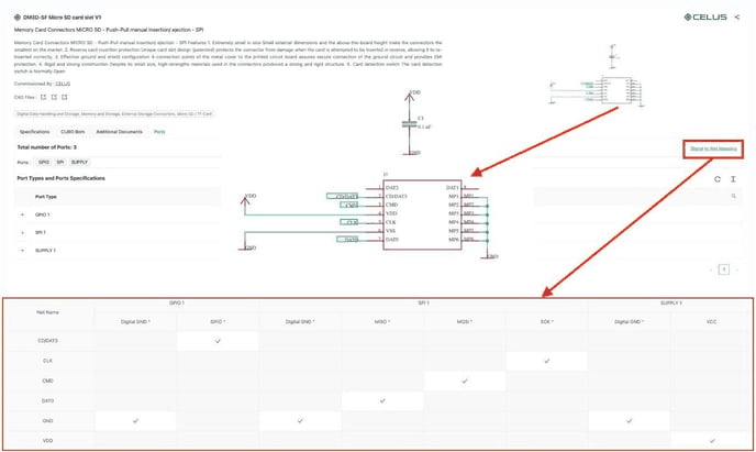
On the CELUS Design Platform, a Port represents a broad concept, which can range from a single signal to standard communication interfaces like I2C, SPI, RMII, etc.
A Port has two main parts: The Port Definitions and Port Specifications.
Here, the Port definition of Signal map defines a specific set of Signals for that particular port. This can vary from the “standard“ signals as per electrical definition. This is done to facilitate the repeatability feature of a CUBO and allow interconnection. This means some signals necessary for a port might be split into other ports. So two or more ports might have to be connected in order to enable one specific Electrical Interface.
Port Specifications refer to the settings of a Port. The Port specifications on a CUBO is the complete list of specification without distinguishing where they are used. (The previous sentence might not be important for DS user). This works on two levels: There is Node specification and Link specification. Node specification is what is unique to the Interface for one particular Functional Block. The Link Specifications are common for any branches connected to that same link. These specifications are used to check the compatibility of the ports with each other.
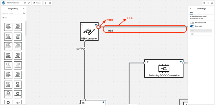
Compatibility defines specific set of validation rules that determines if two or more ports are compatible with each other. These Validation rules are based on the specifications including Port Types to check the compatibility. There are different rules for different specifications.
There are also dependant specifications and dependant ports in which a specification / port is necessary for another one to complete its function.
The nets which have been assigned to signals during CUBO creation will be connected upon exporting the project.
I²C:
I²C is defined by The traditional signals we know for I²C interface along with a ground.
The Signals of I²C are:
Signals
Function
Requirement
SDA
Data line
Required
SCL
Clock line
Reference
Notice that VCC is not included to be part of I²C. This means the user has to connect the SUPPLY port in addition to IIC to have them working.
I²C is only compatible with another I²C port and when connecting two blocks via I²C on the CELUS Design Studio platform, users must ensure that both blocks operate under the same power supply conditions. This is because the platform's criteria for I²C matching require that interconnected blocks have compatible supply voltages. If there is a discrepancy in the power supply between the two blocks, the platform will not be able to resolve and match them successfully through I²C.
UART:
Signals of UART are:
Rx
Receiver Pin
Tx
Transmitter Pin
CTS
Flow Control
Optional
RTS
UART Port is only compatible with another UART port.
SPI:
The condition for getting a working SPI, just like other ports is to have a separate Supply port. However, SPI (and by extent, its derivatives) have one other requirement: There should be at least one GPIO port for every SPI connection with the specification 'Functionality Flag' chosen as 'Chip Select'.
SPI Port is split into three sub-interfaces:
Signals of SPI are:
MISO
MOSI
SCK
SPI is only compatible with another SPI.
QSPI:
The Signals of QSPI are:
IO0
IO1
IO2
IO3
QSPI is only compatible with another QSPI.
SPI 3 Wire:
The Signals of SPI 3 Wire are:
MOMI
SPI 3 Wire is only compatible with another SPI 3 Wire.
SDIO:
The Signals of SDIO are:
CMD
CLK
DAT0
DAT1
DAT2
DAT3
SDIO is only compatible with another SDIO.
ICSP:
In our Platform, ICSP exists in two Variants:
ICSP AVR:
The Signals of ICSP AVR are:
RST
ICSP AVR is only compatible with another ICSP AVR.
ICSP PIC:
The Signals of ICSP PIC are:
MCLR
PGD
PGC
PGM
ICSP PIC is only compatible with another ICSP PIC.
GPIO:
The Signals of GPIO are:
Data Line
GPIO is only compatible with another GPIO.
Supply:
The Signals of Supply are:
VCC
Supply rail
Return path
Supply is only compatible with another Supply.
USB:
The Signals of USB are:
D+
D-
CC1
Channel Configuration
CC2
TX1+
Communication/Power delivery
RX1+
TX2+
RX2+
TX1-
RX1-
TX2-
RX2-
SBU1
Alternative mode data line
SBU2
USB is only compatible with another USB.
Clock:
The Signals of Clock are:
Crystal/Oscillator Clock
Right now, Clock is only compatible with another Clock.
Crystal:
The Signals of Crystal are:
XTAL 1
Crystal Clock
XTAL 2
Right now, Crystal is only compatible with another Crystal.
SWD:
Signals of this port are:
SWCLK
Clock Line
SWDIO
NRST
SWO
Data Line (Note 6)
For now, SWD is only compatible with another SWD port.
RF:
The Signals of this port are:
Signal Line
RF Ports are used for connection between High and low Frequency Radio signals. These include and are not limited to: Radio, Antenna connectors, etc.
RF is only compatible with another RF port.
I²S:
SCK(BCLK)
WS(LRCLK)
SD
I²S is only compatible with another I²S port.
CAN:
CAN H
Signal
CAN L
CAN interface is only compatible with another CAN Interface.
SMBus:
SMBCLK
SMBDATA
SMBALERT#
SMBus is only compatible with another SMBus Interface for now.
PMBus:
PMBCLK
PMBDATA
CTRL
PMBus is only compatible with another PMBus Interface for now.
PCIe
PCIe x1:
PRSNT_1
PRSNT_2
PERST#
HSOP_0
HSON_0
HSIP_0
HSIN_0
REFCLKN
REFCLKP
WAKE#
TCK
TDI
TDO
TMS
TRST
CLKREQ
PWRBRK
At the moment, PCIe x1 interface is only compatible with another PCIe x1 interface.
PCIe x2:
HSOP_1
HSON_1
HSIP_1
HSIN_1
At the moment, PCIe x2 interface is only compatible with another PCIe x2 interface.
PCIe x4:
HSOP_2
HSON_2
HSIP_2
HSIN_2
HSOP_3
HSON_3
HSIP_3
HSIN_3
At the moment, PCIe x4 interface is only compatible with another PCIe x4 interface.
Articles related to
port